3D Printing and its Consumer-level Technologies
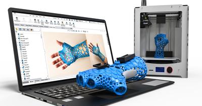
3D printing is a process of manufacturing a three-dimensional solid object from a digital CAD file by successively laying thin layers of material one above the other to build the complete object.
This is a revolutionary and fairly new technology that is redefining manufacturing principles. It can sustainably build products that suit the need and preferences of every single individual.
Thanks to the RepRap movement, this technology is highly democratized and so even kids, students, enthusiasts, and hobbyists have access to the machines either at home or at maker spaces or their respective schools or colleges.
We take a look at two of the popular mass consumer-targeted 3D printing technologies
FDM/FFF
The Fused Deposition Modeling/Fused Filament Fabrication (FDM/FFF) technology is the most affordable and easy-to-use 3D printing technology. Due to the emergence of STEM learning and the compatibility of the technology as a creative tool, 3D printers are now found in every school, college and university.
We will learn more about this technology in the coming sections.
SLA/DLP
Besides the FDM technology, the Stereolithography (SLA) or Digital Light Processing (DLP) technology is also quickly reaching a consumer-level acceptance. The constantly evolving technology and falling prices are making it easier for hobbyists to buy the technology for their use.
The SLA/DLP technologies are fairly similar and differ only in the use of a light source. SLA uses a laser source (point-source) while DLP uses a projector (Light-source). The light converts the liquid polymer resin material into a hardened solid object.
Components of an FDM 3D Printer
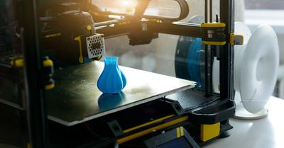
FDM/FFF is the most democratized 3D printing technology. It is used by all types of users from enthusiasts, hobbyists, and students to experts and professional industries. Comparatively, this technology is cheaper than all the other technologies and also easy to work with. A typical FDM 3D printer is simple in design and even students can build one. For a beginner, FDM is the first technology to get started with due to the above-mentioned reasons. And so, we take a look at this wonderful 3D printer and understand its components.
Motherboard
The motherboard is a controlling center of the 3D printer. It is responsible for the efficient functioning of the 3D printer. Like in a computer, the motherboard is the brain of the printer as well. It directs all the other components of the system with instructions while also interpreting the signals to form the different sensors used in the system.
Frame
The frame is the structure in and around which all the components of the 3D printer are housed. The frame delivers stability to the machine and a defined body. Generally, metal frames deliver better stability and robustness to the printer but they also add weight to the system. Acrylic bodies are a good alternative to metal frames.
Build Plate
The build plate is the platform on which the heated material is deposited. Various types of build plates are used including ones made from glass, aluminum, and thermoplastics like PEI (Polyetherimide) sheets.
The build plate, depending on the arrangement, are either heated or non-heated. A heated build plate is better in comparison as it allows for better adhesion, wider material usage, and eliminates warping and cracking issues in some materials.
Extrusion Head
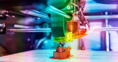
As the name suggests, the extrusion head extrudes the filament/material onto the build plate. The extrusion head is an assembly consisting of multiple critical components but divided into two ends namely, the cold end and the hot end. Both these ends include components like the heater, motor assembly, cooling fan, nozzle, and a range of sensors. We see each of them in detail below:
Cold End
The cold end is called so because it always stays cold in all conditions of the printing process. It is the upper section from where the filament enters the extrusion head. The filament can enter the head either through a direct drive system or a Bowden extruder system.
Direct Drive System: The direct drive is located directly above the hot end. This system typically consists of a stepper motor connected to toothed gears which rotate in opposite directions to pull the filament inside the extrusion head. The filament is pulled and passed on towards the next component.
Bowden Extruder System: The Bowden extruder is located away from the hot end. Typically it is located closer to the spool which is generally situated at the back of the printer. The gear system fulfills a similar function to the direct drive system but since this system is located away from the hot end, the filament has to travel a great distance. To ease this travel, a Bowden tube is used through which the filament safely and accurately passes and enters the hot end. The Bowden tube guides the filament in the right direction.
Hot End
Once the function of the cold end completes, the hot end swings into action. The hot end aims to heat the filament and make it pass through the nozzle.
Heater: The heater is used to heat and melt the filament. In an FDM 3D printer, polymer materials are used which are melted. A thermistor in the system constantly measures the heat and continuously sends signals to the motherboard to maintain the heater temperature to ensure that the material is uniformly heated.
Nozzle: After the heater, the material passes through the nozzle. The nozzle can be of varied materials (steel, brass, ruby tipped, and tungsten carbide) and diameters (0.1 to 0.8mm) depending on the requirement and preference of the user.
Cooling Fan
The cooling fan is an important element of the printer. Once the melted material is deposited on the build plate, then the material should also be cooled before the next layer is deposited on top of it. For this a cooling fan is essential. Without a cooling fan, the prints can lose shape and initial layers may succumb under the pressure of the upper layers. But sometimes for some materials (like ABS), the cooling fan is not recommended for the initial few layers.
Filament/Material
The filament is the raw material consumed by the printer to create an object. The filament is a thermoplastic polymer material wound on a spool and generally located at the back or in some 3D printers on top of the frame.
Working of an FDM 3D Printer
Now that we have understood the components of a 3D printer, it will be easy to explain the working of an FDM 3D printer. So let’s dive into it right away.
FDM 3D printers are commonly built to follow the Cartesian coordinate system of operation. This means that system used the Cartesian coordinate system to move the extrusion head and the build plate to achieve a successful printing operation. An FDM 3D printer consists of three rails that correspond to the three axes (X, Y, and Z). Most commonly, the extrusion head moves in the vertical Z-axis while the build plate moves in the horizontal X- & Y-axis. Alternatively, the system can also be programmed to move the extrusion head in the X- & Y-axis and the build plate in the Z-axis.
The first step to starting the 3D printing process is to load the filament spool onto the 3D printer. The filament is available in two popular diameter variants – 1.75mm and 2.85mm. Depending on the nozzle used in the printer, the correct filament is loaded into the 3D printer. The filament is then inserted into the extrusion head, either through the direct-drive system or the Bowden system.
Once the filament is at the hot end, the actual process of 3D printing starts. As the printer is given the command to start printing, the motherboard first sends a signal to the heater to heat the filament. The ideal heater temperature is achieved depending on the filament used (approximately 190 OC for PLA, 220 for ABS OC, etc.). Once the melting temperature is achieved, the printing process starts.
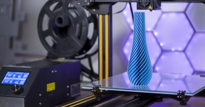
The melted material is then extruded through the nozzle and is deposited onto the build plate. The movement of the nozzle is controlled by the motherboard and is in line with the geometry of the model as defined by the slier software and the gcode file.
The nozzle and the build plate move in sync according to the instructions defined in the gcode file and the first layer is printed. For the next layer, the build plate moves down in Z-direction, or vice versa, the extrusion head moves up in the Z-direction by a height equivalent to the layer thickness set in the gcode file. And the second layer is printed on top of the first layer.
This successive layer-by-layer printing process continues till the entire object is printed.
The printing process does not end here. After the object is printed, the printer stops, the extrusion head moves to its home coordinates and the print is ready to be removed. The print can be easily removed with a small force of hand or with a scrapper. The part will show visible layer lines in the horizontal direction. Generally, they are very prominent and so the object will need post-processing. The object can be post-processed by sanding and acetone vaporing to smoothen the surface, priming-painting to increase its aesthetics, and electroplating to improve its strength.
3D Printing Workflow
Though the knowledge of the components and the working of a 3D printer is essential, it is not complete without fully understanding the workflow of 3D printing. Only after knowing the workflow will any user be able to decide on how to incorporate the technology for his/her personal/professional use.
We take a look at the complete 3D printing workflow:
Design
Designing is the first step in the 3D printing workflow. It is also the single most important element of the workflow without which the process cannot proceed even by a tiny bit.
The design first starts with a 3D design which is then converted into a 3D design. This 3D design forms the base for most of the processes involved in the printing, material, and analysis calculations and so the design has to be as accurate as possible.
Since design is the most important and first stage in the 3D printing process, it puts a lot of onus on designers. Moreover, designing also varies according to the applications and sectors.
Design on your Own
Designers skilled in design software applications can simply design the models they need. Most organizations have proprietary products and designs and so they have skilled design teams to design any part they need and get it 3D printed. Such organizations can also take the help of professional design service bureaus who help in custom designing for the specific applications, processes, and materials considering the tolerance, shrinkage, and other factors.
Designing is not limited to professional users. Enthusiasts, hobbyists, students, and even new learners can try out software applications (many are offered for free) like Tinkercad, Selfcad, etc., to design their models.
Download CAD Files
While the design is important, it is also a fact that not everyone is a designer or not everyone can become one. So for users who are not designers or cannot design every single part they need, there is a solution. Users can access online design repositories that have thousands of designs made available by an active maker-designer community. Most of these designs are freely available (or for minimal prices) for personal use and can be easily downloaded.
Users can take advantage of such repositories to download CAD files which they can print on their 3D printers.
Some of the popular online 3D printing design repositories are Thingiverse, MyMiniFactory, Pinshape, Cults3D, etc.
3D Scanning
Another way to get a CAD file is to reverse engineer a product. When you can’t design or get a downloadable file online, then the last resort is to 3D scan an existing product. The process requires a certain level of skill and a lot of post-processing once the scanning is done but it can yield reliable results. This technique is generally employed in the case of obsolete parts, very critical and complex parts that cannot be dimensionally measured and thus designed with ease. 3D scanning makes it relatively easy to scan and clean up the model rather than design it from scratch.
Photogrammetry
Photogrammetry is the art of deriving measurements and models from photos/images. Photogrammetry is a relatively new field and more so for consumer use. The technique is used for geographical surveys and mapping but was not accessible or easy to use for regular consumers. But thanks to the development of free and affordable software, anyone can use the software today to convert simple images to a 3D model.
This software eliminates much of the tedious process of individually clubbing the images but it also requires the post-processing part. But overall, it will deliver fairly good models.
Slicing & File Preparation
Once you have crossed the stage of getting a 3D Model, then we come across the next element of the workflow – Slicing and File Preparation.
Slicing is the process of cutting the 3D model into multiple layers (slices) of equal thickness. These layers are ultrathin (in microns) and can be considered as the conversion of the 3D model into numerous 2D slices. By printing these 2D slices on top of one another we get the final three-dimensional object.
The slicing is carried out in Slicing software. The operation is not as simple as just slicing the model but it involves careful assessment of a range of factors/parameters to ensure that the final model is successfully printed. This is what we call file preparation.
So, the process is to load the 3D model into a slicer, (the software) and optimize parameters like scaling and orientation, layer thickness settings (layer, top/bottom layer, shell), temperature settings (filament and bed), bed adhesion settings (brim and raft), retraction settings, speed settings (print and travel), infill settings (density and pattern), support settings (density, pattern, and speed), etc.
In addition to this, the user should also configure his/her 3D printer into the slicer and cross-check the material settings (diameter, ideal temperature, recommended bed temperature, etc.)
This extensive file preparation is essential to get a good quality print. Some slicers can also be connected to the printer and files can be directly uploaded into the printer to start the printing process.
Materials
Materials are the basis of any manufacturing process. Unless the material is selected or decided upon, no process can be completed. It is the core consumable that a 3D printer needs.
An FDM 3D printer consumes thermoplastic polymers like PLA, ABS, PETG, Nylon, ASA, PVA, HIPS, TPU, etc. These are the materials that can be converted from a solid-state to a liquid state and back again without significantly affecting its mechanical properties. As a result, in the 3D printing process, the solid thermoplastic filaments are melted and deposited onto the build plate only to be solidified again on cooling to form the object.
All materials are different in their properties and users need to carefully choose the materials according to their applications. You should check out our comprehensive article on the available materials for 3D printing. In addition to the material availability, each material has varied mechanical and thermal and even shrinkage properties, and their behavior is different under different temperatures. By carefully understanding the advantages and drawbacks of each material, the ideal one should be selected.
Lastly, thermoplastics are inherently hygroscopic, which means they absorb moisture. Moisture is an enemy of the printing process and care should be taken to ensure that the material is stored in a cool and dry place. The filaments can be stored in airtight containers with pouches of silica gel to absorb any remnant moisture. Dedicated products like filament driers are also available to safely dry materials before each use.
The material chosen for 3D printing and the object is then loaded onto the 3D printer. Some 3D printers have a filament mount at their back, some have it at the top while professional printers have a separate compartment to carry filament spools.
3D Printing
After all the things are taken care of, we reach the 3D printing stage. The 3D printing stage is complex and depends a lot on all the factors before reaching this stage like the design, the slicing and file preparation, and material choice. Additionally, it also depends on the 3D printer. A professional printer may not cause problems but a desktop or a DIY printer may well prompt many issues and the user will have to troubleshoot them to finally get the model printed. Generally many new users or users using DIY printers eagerly wait and observe the first few layers of their prints to ensure the print will continue smoothly.
The printer may show up layer adhesion problems (the single-most common problem), or other issues like over- and under-extrusion, warping, curling, cracking, gaps and holes, stringing, and a host of other problems. Some will not affect the print much and can be mitigated through post-processing but some others will impact the print quality and users will have to stop the print altogether.
So, be ready to face such issues but there is good news here that all these issues are easy to solve. With some experience and learning and reading, users can stay ahead of the problems and ensure a successful print each time.
Post-Processing
The last and essential element of the 3D printing workflow is post-processing. Often overlooked or less talked about, this stage is very important and goes a long way in the efficient functioning of the 3D printed object.
FDM 3D prints have a rough surface finish, the surface finish is not smooth and the layer line is visible. While sometimes these lines are desirable but most often, not. Post-processing is not only about the looks of the model but it also delivers additional strength to the model and can make a difference in making or breaking the object in the long run.
It is observed that most users need some or the other form of post-processing technique to achieve the desired objectives from the part.
The common post-processing techniques are as follows:
Support removal
Support removal is the basic post-processing activity needed for most 3D prints. It includes removing the part from the build plate and then also removing the support structures used in the part. Support structures are just elements used in the printing process to aid the actual object. They do not have any other relevance and are a waste. These must be carefully removed so as not to break the parts they are attached to on the final object.
These can be removed by a tiny force of hand but critical sections can be cut off by cutters.
Sanding
Sanding involves smoothening of the surface using sandpapers of varying grits. The ideal process is to start with low grit sandpaper (usually 150 grit) and moving towards higher grit sandpapers (2000 grit). This process will sand off the surface layers to give a smooth finish.
Vapor smoothing
Another way to smoothen a part is by vapor smoothening. This requires a chemical called acetone. The 3D printed object is exposed to the acetone fumes in an enclosed environment and the fumes are strong enough to melt the outer layer of the object. This leaves the part with a smooth and glossy surface finish.
There are certain drawbacks to this process, however. This can be carried out only in the case of ABS material. Additionally, since the amount of material melted cannot be controlled, this technique cannot be employed for parts where dimensions are of the essence.
Priming & Painting
To improve the aesthetic quality of a product, users can use primers on the part and after a few successive layers of a primer, the object can be painted (with brush or spray). This can give multi-colored objects.
Hydrographics
Hydrographics delivers a result similar to painting but it is much more controlled and professional and the designs are much more organized. Hydrographics can also be employed for coloring the object with abstract patterns.
Electroplating
To increase the aesthetics and the strength of the 3D printed object, users can try electroplating. By electroplating, the metallic surface on the object not only gives a cool aesthetic look and feel but also imparts additional strength to the object.
