Getting the First Layer Right
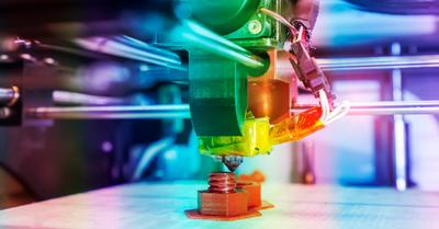
As with many things, when 3D printing, how you start makes a big difference in the final product. That is why it is so crucial that your first layer is printed correctly, as a foundation for the rest of the printed product. When you first work with a new M3D printer, one of the first things you will need to do is manually adjust how the printer produces the first layer.
The first layer is the initial checkpoint for calibrating an M3D printer, although it is far from the only step. Wait until you have figured out the first layer before continuing on with the rest of the guide and fixing the other calibrations on the printer because they might not be correct after you have set the first layer.
What Issues Occur When the First Layer Is Not Calibrated?
If the first layer does not stick well to the print bed, your entire model will be unstable. The print bed gives your product stability during the process. The materials used in 3D printing are heated up to their melting point in order to let the layers mesh with each other and build the final product. However, that melted material is not very sturdy before it solidifies.
If your first layer is blobby and squished, you cannot build the rest of the model on top of it. As noted above, the first layer is the foundation for the entire product and will need to support all of the subsequent layers. Otherwise, the other layers will fall through the initial melted layer, and you will end up with something resembling a modern art installation.
Both of these problems are caused by the extruder nozzle being at an incorrect height. If the nozzle is too close to the print bed, you will create a squished, unusable first layer. If the nozzle is too far away, the first layer will not be thick enough and will fail to adhere to the bed. Essentially if the first layer is not right, then the entire print will be wrong.
Your first step when preparing to use an M3D printer, therefore, is to measure the height of the extruder nozzle and to ensure that it is the correct distance from the print bed so that whatever you are printing will come out with a stable base and that it will stick to the printing bed for the duration of the printing process.
What Do I Need to Calibrate to Fix My First Layer?
If you have performed a test print with your new M3D printer and noticed that your first layer either is not sticking to the print bed or that it is squishy and unable to hold up the other layers of the printing, you should stop the printing before you waste any more materials and check the measurement of your Z offset.
First layer issues are caused by the extruder nozzle being either too close or too far from the print bed. The height of the nozzle when it begins printing the first layer is known as the Z offset. To achieve a perfect first layer, the Z offset is what you will be calibrating. The ideal Z offset is a 1-millimeter gap between the extruder nozzle and the print bed.
While printers are supposed to come with this default, the slightest imperfection in the printer bed or nozzle can put this measurement off. This is not the fault of the manufacturer but is more likely a result of shipping. While the manufacturer probably set the Z offset to 1-millimeter, moving the machine around can easily modify that measurement.
When working with such tiny measurements, you will need to check the Z offset in more than one location. The right upper corner of the print bed may differ from the bottom left corner. Calibrating a Z offset involves adjusting the Z offset in 5 different locations: the center and four corners. It is crucial that the measurement is the same for all spots.
How Do I Calibrate the Z Offset?
The printer assumes that it is calibrated to a 1-millimeter gap between the print bed and nozzle. You will need to adjust the nozzle height manually if there are issues. To do this, you will need a 1-millimeter thick object. A piece of paper or a post-it note is ideal. From here, you will need to find the pane where you can manually adjust the Z-axis height.
From the GUI, this would be under a pane titled calibration. From the spooler, it would be under advanced options. Please note that these option titles or where they are located may differ depending on your model. Regardless there will be an area where you can adjust the Z-axis height. Now you are ready to calibrate.
The general idea is to move the nozzle to each of the five areas you need to calibrate (the center and four corners) and then use the piece of paper to check and adjust the nozzle height.
You should be able to slide the paper between the nozzle and print bed while feeling resistance. Oftentimes being able to hear the paper scraping the nozzle is a good sign.
If the paper cannot move at all, the nozzle is too low. If the paper moves freely, and you cannot feel resistance, then the nozzle is too high. Once you have determined the correct height, do not forget to apply the changes to your printer’s settings. You may need to do this via a G-code or with a simple push of an apply button, depending on your printer model.
Testing Your Z Offset Calibration
While the piece of paper will give you an excellent feel for what adjustments need to be made, you are not done calibrating your z offset until you have printed a test border. Printing a frame around the edge of your print bed will allow you to see if your calibration efforts were successful.
A properly calibrated printer should have a thick even test border.
There should be no blobs or noticeably thinner areas. Please note that your test border corners may be lighter or thicker because of the extruder stopping to change direction. If your test border appears thin, then the extruder nozzle is still too high. If your test border has blobs, then the test nozzle is too low. You will likely need to try calibrating again.
It might be frustrating to return multiple times to recalibrate the Z offset, but it will be more than worth it when you finally achieve an even, thickly laid border for your first layer. Knowing that your M3D printer is doing what it should be will give you the confidence to get working on your first ever project with it.
Make sure that you have enough of the filaments in order to do thorough testing of the M3D printer. This article discusses more about filaments and how they work in the process below. Still, you will need enough materials to allow yourself to test the printing process several times during the calibration process.
Calibrating Your Z Offset: A Step by Step Guide
If you do not need to know the science behind every step along the way and want to get calibrating already, here is a step by step list of how to calibrate the Z offset. With these five easy steps, you will be well on your way to using your M3D printer and doing your ideal printing projects.
- Prepare to calibrate by finding a piece of paper and pulling up the area of your printer settings that allows you to adjust Z-axis height.
- Tell the printer to move to the center. Insert your piece of paper and adjust the nozzle’s height until the paper can slide in and out but still meets resistance. Apply this change to your printer settings.
- Get the printer to move the nozzle to one of the corners. Insert the paper again, and lower or raise the extruder nozzle until the paper can move with felt resistance. Apply the change. Repeat with the remaining four corners.
- Return the nozzle to the center, and recheck this setting. Make changes if need be.
- Print a test border. If it shows issues, try calibrating again. If it looks good, then you are done!
Adjusting the Motors for Precision
Once you are confident in your first layer, you will need to turn your attention to the printer’s overall movement. After all, the first layer is hardly enough to account for the entire project. An M3D printer controls movement through a three-axis system. To ensure precision, you will need to check and adjust the X, Y, and Z axes.
3D printers do not have sensors, so they work primarily through assumptions. The computer tells the printer to move the nozzle 100 millimeters to the right, and the printer attempts to do it. The printer and computer have no way of knowing if this movement was correct or not. It will continue undeterred whether it moved 100 or 1000 millimeters.
3D printers are rarely off by so much, but when printing a 3D model, the difference between 100 and 99 can create a sloppy result. Remember that the printer assumes it is correct, so it will continue to compound movement errors without making any corrections. Most people print very small projects so that one millimeter can be pretty significant.
The movement of an M3D printer is controlled through stepper motors. When you calibrate a 3D printer’s movement, you are adjusting how much the motor moves based on a command from the computer. These stepper motors move through steps, as the name implies. The printer’s use of these steps allows for very fine control.
The X-Axis
As noted above, the stepper motors move in steps, not measurements like millimeters or inches. You can begin by checking the movement of the extruder along the x-axis. You will need a caliper for measuring how much the extruder actually moves compared to how much you told it to move. The computer will say ‘move 20 steps to the right,’ and then you must measure it.
For people who have not taken algebra in a while, the X-axis refers to moving left and right along a straight line. How far did 20 steps move? Was it a millimeter? Half a millimeter? By knowing how many steps equals a millimeter, you can understand exactly how to program the printer to do your project.
If your printer needs to move 80 steps to move a millimeter, you should note that number down for future reference. To check movement, there are a couple of approaches you can take. You can simply move the nozzle and mark the positions it moves to or print a simple test object (such as a cube).
If your cube’s measurements in real life do not match up with the supposed sizes you should have seen based on the number of steps your printer took; you will need to recalibrate it. You can use commands to instruct the printer that 20 steps do not equal one millimeter and that, instead, the nozzle must move 20.46 steps to complete that measurement.
The Y Axis
The Y-axis refers to moving up and down along a straight line in a 2D grid. Recalibrating the Y-axis works in the same way as for the X-axis listed above. Print a test cube and then measure it in the Y-direction to ensure that it printed the size you were expecting. You may need calipers for these tiny, precise measurements.
Your printer will tell you how many steps it took to print your cube for each axis. If 20 steps supposedly extrude one millimeter, but 100 steps only gave you a cube with a 9.5mm Y-axis, you know something has gone wrong. You will need to use the formula to determine the correct number of steps. It is as follows:
Correct Steps = 10*20 / 9.5
In this case, the correct number of steps is 21.05. That may not seem like a significant increase, but if you remember what was noted earlier, with such tiny projects being printed, even a fraction of a step can make all of the difference with your final product. Even if your first layer looks perfect, slightly off-kilter measurements can ruin the entire project.
The X and Y-axes allow you to test out your printer’s first layer, and if you noticed that your initial layer still is not the right measurements even after you adjusted the nozzle height, the problem might lie with these axes. Once you are sure that the nozzle is correct for the first layer, try measuring these to determine the difficulty.
The Z-Axis
As noted above, the Z-axis refers to moving forward and back along a straight line. Your Z offset is how far from the print bed that your extruder nozzle starts at, but the nozzle will need to continue along the Z-axis as it prints your project because, with each successive layer, the project will become taller.
The Z-axis can also be recalibrated using the same method as suggested for the X and Y-axes. Hopefully, your printer’s number of steps taken for the Z-axis part of the cube will be accurate to the millimeters you have printed, and you will not need to recalibrate. If you do, remember to send that second command so that the first one is saved in the printer.
The Z-axis is a bit tricky as compared to the previous ones because your printer might not allow for many variations in it. As addressed in depth below, you might have to manually edit some of the code pertaining to the Z-axis if you want to see the full spectrum of what your M3D printer is capable of doing, so be patient with it.
Filament Settings
A critical aspect of testing is how many steps your motors need to take in order to get through a certain amount of filament. For example, if your printer says that it needs to take 50 steps to print one millimeter of filament, then you will need to test whether or not that is accurate. After all, you want to know how much filament each project will require.
If you take a length of the filament and markdown where 30mm is on the filament and then feed it into the printer, you can test the printer. Print 5mm and see how many steps the printer has registered. Then check the measurement from the marked spot to the top of the extruder. If you have 25mm of filament remaining, and your printer shows 250 steps, then your printer is just fine.
If not, you will need to adjust the filament settings. You will need to send a new command to the printer for the correct number of steps it needs to print out one millimeter and then send a second command to save that data. Do not forget that the second command or your printer will not be correctly calibrated and will continue to make the same mistake as before.
In order to calculate the correct number of steps your printer needs to print out 1mm of filament, you can use a formula. The right number of steps equals five times the incorrect number of steps your printer gives you, divided by the total amount you marked minus how much was left. In numeric terms, it looks like this:
Correct Steps = 5*50 / (30-25)
Diameter
As you might have already discovered, there will inevitably be some variance in the diameter of the filament spools on offer between batches and companies. No spool of filament will ever be exactly the same as another, although the allowed range within a single brand and color is usually small enough to be compensated for.
Given that information, you should always use calipers to measure your filament before starting on a project. For calibration purposes, you will need to know the diameter of the filament before inserting it into the printer so that it can accurately print the correct amount of filament. When finding the diameter, it is best to measure the filament in a few places and take the average.
Each brand will give you a tolerance range of the filament diameter, but it is better to do the measuring yourself and find the average for your slicer. After all, 3D printing heavily relies on precision. Using a range or best-guess from the manufacturer is a lot less reliable than your own calipers and averaged measurements from three to five places on the filament.
A good brand will give a tolerance of 0.05mm or fewer, although you should always check consumer websites like Amazon that have honest reviews. Just because a manufacturer claims something does not mean it will turn out to be true. You might also be unlucky enough to end up with a bad batch of filament that has some inherent problems.
Temperature
Determining the correct temperature for your filament is a tricky challenge that can only really be found through trial and error. Although brands will list the best temperature on the packaging, it is often a range and does not account for your particular printer model. Some printers have heated printing beds, and others do not.
The brand may only list the minimum heat required, aka the melting point for the filament, which gives you a baseline, but not much else. In order to test your filament at multiple temperatures, you can download the pattern for what is known as a “temperature tower,” which dictates that each layer of the tower is printed at an increased temperature.
By carefully examining each layer of the tower and observing the printing process, you will undoubtedly notice which layers mesh well together and which ones are too sloppy or burnt. Once again, though, you must take your model of the printer into account. Depending on your model, the printer may not allow you to print at different temperatures for different heights.
If that is the case, you will need to go through and manually enter new commands for your printer in order to allow the process and the variations in temperature. The best way to test is to have a five-degree difference in temperature for each ascending layer; enough to see a difference, but still small enough to be precise.
Testing Your Calibration Settings
You have finally gone through the rigorous testing processes explained above, and, lo and behold, you are finally done. Your printer correctly calculates the steps for printing one millimeter of filament on every axis, you have input the filament diameter, you know the right temperature for printing, and your nozzle starts at the perfect height. Voila!
Unfortunately, you are not entirely done. Even after inputting all of that data, printing small cube after small cube might not be enough of a challenge to find out if there are any other calibrations needed for your printer to do everything it is capable of. So-called torture tests exist on the internet to put your M3D printer through the paces.
You can often download these files, which involve much more complicated designs than the test cube, and see how the printer handles these new challenges. After all, you are probably planning on printing things that are more interesting than a plain cube every time, right? Each torture test works with different parts of the printer’s calibrations.
That means that even if it successfully completes one of the torture tests with flying colors, there may still be an underlying issue that you simply have not discovered yet. It is always better to find these things on test projects before you start on your real printing project so that you do not end up wasting time and expensive materials.
Conclusion
If you have recently purchased an M3D printer, you will need to check to make sure that it is correctly calibrated. Whatever the manufacturer claims, testing the measurements beforehand will ensure that your printing projects are successful, and you do not end up wasting your own time and materials on something with a serious flaw.


